Getting Started with Airlytix: Assembly
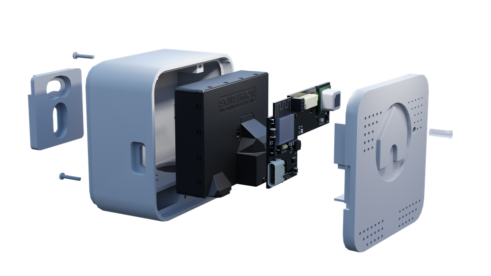
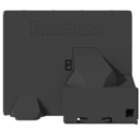
Most ES1 devices ship fully assembled. If your unit already looks like the render above and the front indicator light is visible, you can skim this page or move straight to WiFi setup.
If you are assembling or printing a case yourself, this guide will walk you through:
- Checking you have all the required parts
- Printing the case (if needed)
- Assembling the electronics and case
Typical time to complete: 20–30 minutes once all parts and tools are on hand.
Recommended tools:
- Small Phillips screwdriver suitable for M1.6 screws
- Optional: tweezers for handling small inserts and screws
- Optional: drill and wall anchors if you plan to mount the wall clip to masonry or plasterboard


Assembly Steps
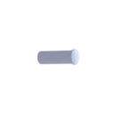
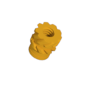
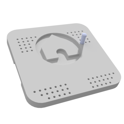
Press the light guide into the case front
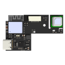
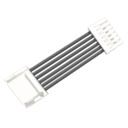
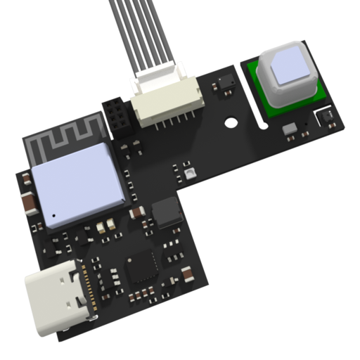
Attach the connector cable to the PCB
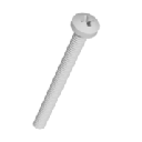
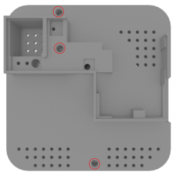
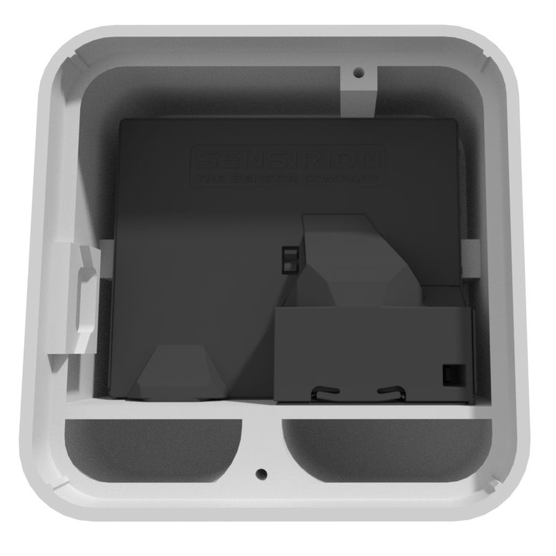
Place the PCB into the case front and secure with the M1.6x4mm screw

Connect the other end of the connector cable to the sensor module

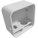
Place the sensor module into the case body
Screw together the case front and back using the two M1.6x20mm screws
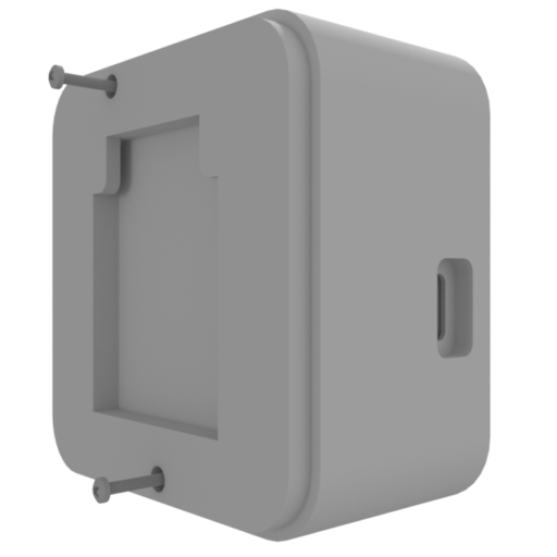
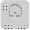
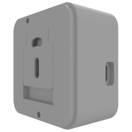
Place the wall mount into the back of the case
Check your assembly
Your ES1 is correctly assembled if:
- The case front and body fit together cleanly with no large gaps.
- The light guide lines up with the front opening and is clearly visible.
- The wall mount sits securely in the back of the case.
- When you plug in USB power, the device powers on and the indicator light or status LED turns on briefly.
If anything looks or feels wrong, re-check the steps above before mounting ES1 on the wall.